Drive Motor Controller - Roboclaw
- Max Voltage: 34 VDC
- 30 Amps Continuous Per Channel
- 60 Amps Peak Per Channel
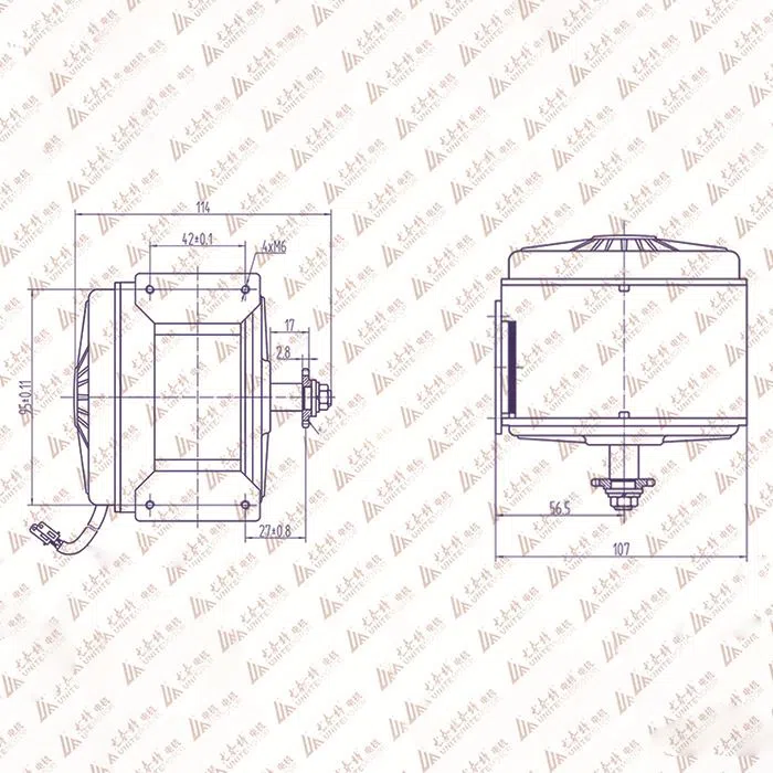
- Motor Type: Brushed DC
Version: V5E 2x30
Firmware: 4.1.34
OEM: BASICMICRO
2x30A Data Sheet
OEM Site
User Manual
Interfacing Components:
Disconnect
The main battery should include a quick disconnect in case of a run away situation and power needs to be cut. The switch must be rated to handle the maximum current and voltage from the battery. Total current will vary depending on the type of motors used. A common solution would be an inexpensive contactor which can be sourced from sites like Ebay. A power diode rated for approximately 2 to 10 Amps should be placed across the switch/contactor to provide a return to the battery when power is disconnected. The diode will provide the regenerative power a place to go even if the switch is open.
Warnings
- Disconnecting the negative power terminal is not the proper way to shut down a motor controller. Any connected I/O to RoboClaw will create a ground loop and cause damage to RoboClaw and attached devices. Always disconnect the positive power lead first.
- Brushed DC motors are generators when spun. A robot being pushed or coasting can create enough voltage to power RoboClaws logic intermittently creating an unsafe state. Always stop the motors before powering down RoboClaw.
- RoboClaw has a minimum power requirement. Under heavy loads, without a logic battery, brownouts can happen. This will cause erratic behavior. A logic battery should be used in these situations.
- Never reverse the main battery wires, Roboclaw will be permanently damaged. Never disconnect the motors from RoboClaw when under power. Damage will result
- When wiring encoders make sure the direction of spin is correct to the motor direction. Incorrect encoder connections can cause a run away state. Refer to the encoder section of this user manual for proper setup
- A voltage clamping circuit is required to correct any regenerative voltage issues when a power supply is used as the main power source
- Never reverse the main battery wires, Roboclaw will be permanently damaged.
- Never disconnect the motors from RoboClaw when under power. Damage will result.
General Settings
IO
S3 Mode: E-Stop (Inverted)
- The E-Stop is designed to be Open Wire Fault Fail Safe. For example if any wires are in inadvertently disconnected, the E-Stop will activate.
- S3-SIG pin has a 1k Ohm pull-up resistor S3-PWR. The E-Stop is activated by an the Arduino Nano pin_2 in INPUT mode set to LOW. The E-Stop is deactivated by an
Notes
The roboclaw manufacturer warns against removing the electrical power from the moto controller as this would still allow the motor to spin and generate power and possibly cause regenerative voltage issues. The roboclaw can will have voltage clamp installed to limit the regenerative voltage feedback to the main power bus but it not yet understood if this will work once power is removed from the roboclaw (#todo Test the voltage clamp with out power supply to roboclaw)
VClamp
https://downloads.basicmicro.com/docs/vclamp_datasheet.pdf#page=5
Resistor Selection
The resistor needs to be sized based on the running voltage and potential current that will need to be dissipated. Below is an example chart of potential resistor values and wattages. The resistors can be sourced from suppliers such as DigiKey. The excess energy will be turned into heat. The recommended resistors below have an aluminum shell for mounting to help dissipate the excess heat.
source: systems/drive-system/vclamp-resistor-selection.csv
RoboClaw and MCP Software Setup
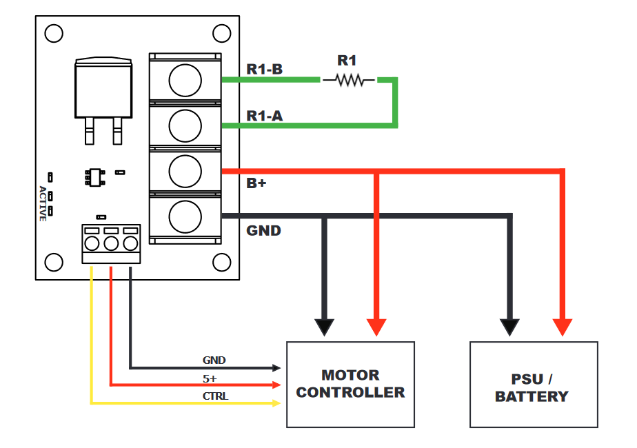
Each of the auxiliary pins on RoboClaw or MCP have a drop down option in Motion Studio. One of these options will be VClamp. Set the desired auxiliary pin to VClamp and select the invert option for the pin. Then set the battery maximum voltage to at least 1 to 2 volts above. Refer to the VClamp application note for more information. Wiring The wiring schematic below illustrates how to properly wire the VClamp. R1 is the braking resistor. R1 will turn the excess energy into heat. The VClamp can be controlled directly by the motor controller or separate control system such as an external microcontroller. B+ and GND from the main screw terminal connect directly to the motor controller power source. The below schematic outlines the basic setup for VClamp. It does not take into account proper safety such as a fuse or contactor in the system. Refer to the motor controller’s data sheet, manual and application note