


Wire System
The the wiring of each major electrical system is documented with https://www.diagrams.net/ via .drawio or .drawio.svg See FAQ for file format details. The construction of individual wires and harnesses is documented with WireViz via .yml files. The .yml files are stored in the wireviz directory and are processed into .svg files with the VScode Task "Run wireviz" using the shell script wireviz.sh
- WIP
- 24 Volt System Diagram (mostly complete)
- 12 Volt System Diagram (incomplete)
- Wiring construction (incomplete)
- Part documentation (incomplete)
- Wire lables (incomplete)
- Topics on how properly properly reference and annotate everything from a single circuit board to a collection of complete enclosures.
- https://en.wikipedia.org/wiki/Reference_designator
- https://www.cosjwt.com/tag/asme-y1444-2008/
- IEEE-200-1975 (ANSI Y32.16-1975)
- Obsolete Reference Designations for Electrical and Electronics Parts and Equipment
- ASME Y14.44-2008
- Renewed Reference Designations for Electrical and Electronics Parts and Equipment
- MIL-STD-1472H (Human Engineering)
- Ideal spacing, size, dimension, and symbols for switches
- NASA Workmapship Standards
- NASA Wire and Cable Workmanship
- WireViz syntax
- Relay Pin Numbering
- Regenerative Braking Safety
- Siemens Symbols Library
- The movable (less fixed) connector of a mating pair shall be designated P [where P means plug].
- The stationary (more fixed) connector of a mating pair shall be designated J or X [where J means Jack].
- If two cables are to be connected to each other, each of the mating cable connectors shall be designated P.
24 Volt Wire System
Labeling Convention `
- Wire id: Specifies a wire harness (maybe a single or multiple conductors)
- Port-id: Specifies a wire port (Always at least 2 per wire harness)
- Mate-id: Specifies a mating connect (Always a least a single matching pair)
DC cable sizing calculator
Voltage (V): 24
Current (Amps): 30
Cable run, including return (m) : 2 (6.65 feet)
Voltage drop (%): 3
Calculated Minimum cable cross section (mm^2): 4
Closest American (AWG) gauge: AWG 11
Parts
- 24V Battery (2x12VDC)
- 24V Battery Charger
- 50 Amp ANL Fuse and Fuse holder
- Labels:
FH1F1
- Labels:
- Main Battery Disconnect Switch
- Label:
S1
- Label:
- 24V SLA Charger Switch
- Label:
S2
- Label:
- DIN Rail Terminal Blocks
- Label:
TB1
- Label:
- Voltmeter Gauge
- Label:
- Brushed DC Motor Controller
- Label:
Roboclaw V5E 2x30
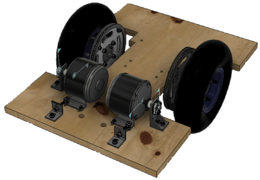
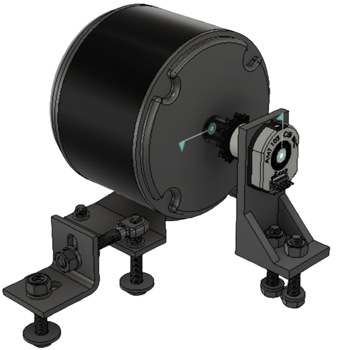
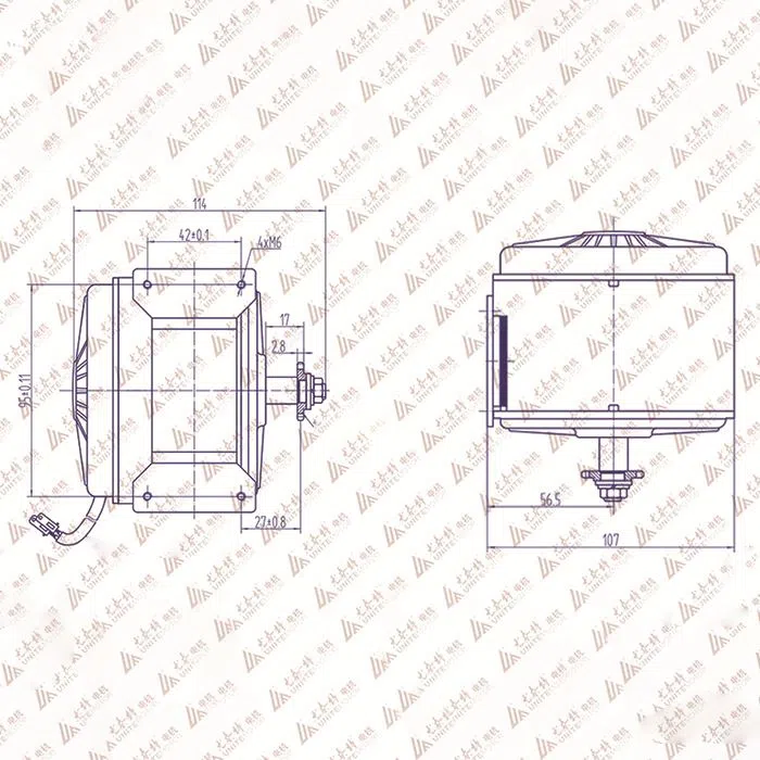
- 2x DC Motors
- Label:
MY1016
Power System Concept
The power system is responsible for safely supplying power to the loads while also isolating other devices during different modes of operation or charging. This design incorporates on-board chargers that may only connect and charge the batteries under specific conditions. Most low cost off the shelf sealed lead acid (SLA) absorbent glass mat (AGM) float chargers [SLA battery maintainers] require the battery not be under load during charging. The design provides a solution for the following requirements.
Power Modes
- Charging mode: Shall use relays or contractors to isolate the 12V and 24V batteries from the loads. The relays or contractors shall also route power from an on-board 12V power supply to the 12V load such that the on-board computer can remain on during charging operations. The on-board computer (rpi) will have a dedicated UPS/Battery pisugar to operate during power source transitions such as (12V Battery to 12V Power Supply).
- E-stop mode: Shall use an emergency-stop button that disconnects power to the 24V Load and Pre-charge circuit such that the Pre-Charge, Start, and Stop buttons are disabled and Relay Z is opened. When releasing the e-stop button the system shall return to Standby-Mode.
- Pre-Charge mode: Shall provide a Pre-charge Momentary-On push button that supplies a reduced voltage (5V) from the 24V battery to reduced the in-rush current from the capacitive load characteristics of the motor controllers.
- Drive mode: Shall provide a Start button to latches the normally open switch Relay Z closed. Relay Z and Relay C shall be specified to handle at least 24V and 50A. Relay Z shall act as the main power switch to provide 24V to motors.
- Standby mode: Shall provide a Stop button to unlatch the normally open switch Relay Z.
Relay Behavioral Descriptions
- Relay A
- When not energized:
- Isolate the 12V Charger from the 12V Battery Circuit
- Connect the 12V Battery Circuit to the 12V Load Circuit.
- Isolate 12V Power Supply from the 12V Load Circuit
- When energized by the 12V Power Supply:
- Connect the 12V Charger to 12V Battery Circuit
- Isolate the 12V Battery Circuit from the 12V Load Circuit.
- Connect the 12V Power Supply to the 12V Load Circuit
- When not energized:
- Relay B
- When not energized:
- Isolate the 24V Charger from the 24V Load Circuit during Standby Mode and Drive Mode.
- When energized the 12V Power Supply:
- Connect the 24V Charger to the 24V Battery Circuit during Charging Mode.
- When not energized:
- Relay C
- When not energized:
- Connect the 24V Load Circuit to the 24V Battery Circuit to enable Standby Mode and Drive Mode.
- When energized the 12V Power Supply:
- Isolate the 24V Load Circuit from the the 24V Battery Circuit to enable Charging Mode.
- When not energized:
- Relay X
- When energized by the 12V Load Circuit:
- Latch ON and subsequently latch ON Relay Z.
- When not energized by the 12V Load Circuit
- Latch OFF and subsequently latch OFF Relay Z.
- When energized by the 12V Load Circuit:
- Relay Y
- When energized by the 24V Battery Circuit it enables the Start-Stop Latching Relay Circuit such that the start button will complete the Relay X Coil Circuit.
- The main purpose is to act as a stop button to unlatch Relay Z during anytime the Power from the 24V Battery Circuit cuts out. This may occur once the e-stop is engaged or the charging mode is engaged thus not energizing the coil.
- Relay Z
- When energized by the 24V Battery Circuit:
- Connect the power from the 24V Battery Circuit to 24V Load Circuit. The completion of the Relay Z Coil Circuit is dependent on Relay X Contacts, Relay Y Contacts, E-Stop Contacts, Start Button, and Stop Button.
- When not energized by the 24V Battery Circuit:
- Disconnect power to 24V Load Circuit.
- When energized by the 24V Battery Circuit:

24 Volt Supply Wiring Diagram
wire-system-24-volt.drawio.html

12 Volt Supply Wiring Diagram
 ## Glossary
changeover contact